
Introduction
The goal of this project was to design a circuit that takes an audio signal from an AUX cord, isolates the low, mid, and high frequencies using a crossover circuit, and plays it through a set of speakers. A crossover circuit takes an input signal and separates it into low (bass), mid, and high (treble) frequencies. This is useful in many audio applications because speakers are better able to project sound when they only play audio from a more specific band of frequencies.
I wanted to create a master volume control, as well as volume controls for each of the low, mid, and high frequencies to create an equalizer. The speakers I used were Polk Audio Driver MW 6503 for low and mid frequencies, and a Polk Audio SL 2000 for high frequencies. Many advanced crossover designs for speakers can be found online, but I wanted to build my own crossover design from core concepts of passive frequency filtration, using components I already owned.
Design
Stage 1:

Above is the first stage of my design in the LTspice software. The first stage of my design is to create the master volume control. I did this by taking the audio signal from the AUX cord and sending it to a non-inverting amplifier using a 4556AD op amp. In the place of resistor Rpot1 in the diagram, I will use a 10k potentiometer to allow for variable gain of the amplifier. I labeled the output of my design Vamp in LTspice. Using labels from the diagram above, the formula for the gain of a non-inverting amplifier is Gain = 1 + Rpot1/R1. In place of Rpot1, I use a 10k potentiometer.
I send the signal through a blocking capacitor, which blocks direct current, or DC, from the input terminal of the op amp, while allowing the alternating current, or AC, audio signal to pass through. This is important because if a DC signal is amplified beyond the voltage being applied to the power rails of the op amp, the op amp will saturate. This would result in the AC output being clipped.
Stage 2:

Above is my design is the three-way crossover, the second stage of the circuit. The output from the master volume amplifier is first sent to three op amp buffers. This is done to prevent the filter circuits from interfering with each other. Next, I make a lowpass filter, bandpass filter, and highpass filter from resistors and capacitors. The RC high pass filter sends the signal through a capacitor, with a resistor leading to ground. The lowpass filter sends the signal through a resistor, with a capacitor leading to ground. The highpass filter sends the signal through a capacitor, with a resistor leading to ground. The bandpass filter can be built by putting a buffer between the lowpass and highpass filters. Most high-performance crossovers include inductors as well. However, most of the inductors I owned had a relatively high impedance (around 30 ohms), which was too high to properly filter the frequencies. As a result, all three signals are created from RC filters. For the cutoff frequencies of the filters, I calculated RC values that would cut the frequency off at a standard value for low, mid, and high speakers. The appropriate cutoff frequencies for the low, mid, and high speakers are dependent on the make and model of the speakers and can often be a personal preference. Because of this, I had the intention of further adjusting these RC values once I completed the circuit and could hear how the actual audio signals responded to the crossover.
Calculating the RC values: A reasonable cutoff frequency for the lowpass filter was somewhere around 300 Hz, and a reasonable cutoff frequency for the highpass filter was somewhere around 3.3 kHz. For the bandpass filter, I would use the same RC combinations as the lowpass and highpass filters. It was not important for the RC values to produce a cutoff frequency very close to those. This is because, as previously stated, the appropriate cutoff frequencies are speaker dependent, and often a personal preference, so they will be adjusted later. The formula for the cutoff frequency of an RC filter is f = 1/(2*pi*R*C). Because I could be more flexible with resistor values than capacitor values, I solved this equation for R, so that R = 1/(2*pi*C*f). Starting with the lowpass filter, I set f = 300 Hz and arbitrarily chose C = 1 uF. This results in about R = 530 ohms. From this, we can expect a cutoff frequency of 284 Hz. Because of this, I chose C = 1 uF and R = 560 ohms for my lowpass filter. For my highpass filter, I set f = 3 kHz and C = 100 nF. This results also results in R = 530. Because of this, I choose C = 100 nF and R = 560 ohms. From this, we can expect a cutoff frequency of 2.84 kHz.
I then created an isolated diagram of the crossover in LTspice to simulate its frequency response, where I replaced Vamp in the diagram above with an AC source. This is the graph that resulted:

The plot displays the gain in dB vs. the frequency of the source for each filter. A gain of 0 dB essentialy means that the signal will pass through unaffected, where as the more negative the gain is, the more the signal will be attenuated. Because of this, the chart visually looks as I expected. This is because the lowpass filter is at 0 dB for low frequencies, the highpass filter is at 0 dB for high frequencies, and the bandpass filter is at its maximum when neither the lowpass or highpass filters are greater than -3 dB. Below the chart are the data points for the intersections of the low and bandpass filters and the bandpass and highpass filters. The -3 dB cutoff frequency for the lowpass and bandpass filters occurs at 289 Hz, and the cutoff frequency of the bandpass filter and highpass filter occurs at 2.81 KHz. There is very minimal error between the simulated results and my calculations, so this is the crossover design that I proceeded to build.
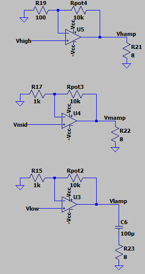
Stage 3:
Pictured right is the third and final stage of my circuit. It includes the three isolated signals each being sent to a non-inverting amplifier. Each amplifier features a 10k potentiometer for variable gain. The output of each amplifier is sent to a different speaker, all of which are 8 ohms. The potentiometers in this part of the circuit will serve as the equalizer for the amplifier.

Building
Stage 1:
I began by building the non-inverting amplifier pictured right. This is the amplifier that takes the input signal and serves as the master volume control. I connected a 1k ohm load and measured the voltage across it to test the amplifier. I applied a sinusoidal input to the blocking capacitor, and measured the output across the resistor with my oscilloscope.


The output of the amplifier is pictured above. The output is being clipped because the op amp is saturating. There were a couple of ways to solve this problem. The first way would be to use a greater blocking capacitor with a higher capacitance to limit the amount of DC that is getting through. I ended up doing this later, but not quite yet. The other way to solve this was to increase to voltage being applied to the power rails of the op amp. The 4556AD op amps are rated to a voltage differential of 30 V. This allowed me to increase the positive voltage to 10 V and the negative voltage to -10 V.

The video above shows the oscilloscope measuring the output of the amplifier when I apply a sinusoidal wave from a signal generator. In the beginning of the video, the potentiometer is set to its maximum resistance. Due to the gain formula of a non-inverting amplifier, this gives the maximum gain. I then lower it to the minimum resistance (for minimum gain) before I return it back to maximum resistance. This demonstrates that the master amplifier of the circuit functions properly, and I can move on to the next stages of my design.
Stage 2:
The image on the right shows the circuit after I added the three filters. The lowpass filter is on the left third of the circuit, the bandpass filter is on the middle third of the circuit, and the highpass filter is on the right third of the circuit. I use a LM324N op amp for the buffers. I send the output of those buffers to each of the filters. After this stage, I was ready to send the output of each filter to their own non-inverting amplifier to create the equilizer.

Stage 3:
The image on the right shows the completed circuit with all three stages. The top left potentiometer controls the master volume. The amplifier in the bottom left of the circuit controls the lows, the amplifier in the middle of the circuit controls the mid, and the amplifier in the rightmost part of the circuit controls the highs. The adjustment of each of those potentiometers serves as the equalizer of the amplifier. The output of the amplifiers are the lowest red wires on the circuit. One wire from the speakers will connect to these red wires, and the other will be grounded. At this point, I was ready to test the complete circuit with audio.

When I tested the bass, I did not hear any audio, and I noticed that my power supply was not supplying the 10 V that it was supposed to. When I saw this issue, I guessed that the two most likely problems were either a short in the circuit somewhere, or that my op amps were saturating. When I took a multimeter and measured the DC values of the circuit, I saw that the output of the lowpass filter equalizer op amp was very close to 10 V. This told me that the op amp was saturating. I measured the DC input of the op amp on the positive terminal, and saw that it ranged from 4-6 volts. This told me that my op amp was saturating due to the amplification of my DC values. The reason why the low audio was having this problem, and not the mid or high audio, was because both the highpass and bandpass filters send the signals through a capacitor, which blocks DC. The lowpass filter sends the signal through just a resistor instead. To solve this issue, I upgraded the input blocking capacitor from 1 uF to 4700 uF, and I put another blocking capacitor of 100 uF at the output of the circuit. This solved the issue and I was then able to hear the audio.


The video above shows the audio when only the bass is plugged in. The volume was lower than I wanted it, so on the non-inverting amplifier, I replaced the two 10k resistors in parallel with a 1k resistor to increase the gain. Notice how the vocals are very weak relative to the music, and how the drum makes a thud sound. There was also the presence of a low humming sound, that does not come through well on the video recording. These results were enough to make me satisfied with the cutoff frequency of the bass. When viewing the videos below, ensure that the videos you are not currently watching are muted to avoid hearing audio from multiple videos.

The video above shows the audio when only the treble is plugged in. The volume was particularly low, so on the non-inverting amplifier I replaced the two 10k ohm resistors in parallel with a 100 ohm resistor to increase the gain. In my opinion, the primary synth was too strong relative to the vocals and the high pitched ringing. In order to fix this, I needed to raise the cutoff frequency. By replacing the 560 ohm resistor in my highpass filter with two 1k ohm resistors in parallel (for 500 ohms), I could raise the cutoff frequency from 2.84 kHz to 3.18 kHz. I tried this, and the result is below:


The video above also shows the audio when only the treble is plugged in, after I replaced the 560 ohm resistor of the highpass filter with two 1k ohm resistors in parallel. I was definitely satisfied with these results, as I could hear the vocals much clearer than with the previous resistor values.
The video above also shows the audio when only the mid is plugged in. Similar to the bass, on the non-inverting amplifier, I replaced the two 10k resistors in parallel with a 1k resistor to increase the gain. I also replaced the 560 ohm resistor from the highpass filter section of the circuit with two 1k ohm resistors in parallel. Notice how the primary synth is very audible. The vocals are also less audible than the treble, but more audible than the bass. I was satisfied with these results so I proceeded to the final demo.
Final Design, Demo, and Conclusion

The master volume didn't have as much gain as I wanted so I changed the 10k ohm resistors in the non-inverting amplifier to a 1k ohm resistor.
I was definitely satisfied with these results, especially because I made the design from scratch using filter and amplifier circuits I learned about in class, rather than using a design from the internet. I also managed to make the circuit without ordering any specialty parts. Everything I used in the circuit I owned previously. I thought the most challenging part of the circuit was figuring out which RC combination would make the most ideal cutoff frequency. I had a lot of fun making this project, and I would love to make another amplifier in the future. Next time, I would probably order specialty parts and possibly get more help from the internet to optimize the audio quality. I would also make it dual channel audio, where I have a set of left speakers and right speakers with different audio. I would also be tempted to solder it onto a board as well, so it would be more permanent.


Note: If I were to redo this project, one change I would make is I would add blocking capacitors to the mid and high speakers. This because electrolytic capacitors before the speakers would do a better job than disk capacitors from the filters for ensuring the speaker isn't negatively affected by DC.