
Introduction
The goal of this project was to design and build a circuit that functions as a timer with a selectable time using a microcontroller, or MCU. The user would input the desired time in binary using a series of switches, and then multiple LEDs would represent the time remaining in binary. An LED that is turned on would represent a 1 and an LED that is off would represent a 0. The user would be able to watch the time decrease on the LEDs before an alarm sounds when the time runs out. I also wanted start and stop buttons to operate the circuit. The start button would indicate when to start the timer, and the stop button would stop the countdown mid way, as well as the alarm when it goes off. I wanted to use a MCU with a very similar design to the Arduino Uno, and program it in the Arduino IDE app. The image below does a good job of showing how binary numbers can be converted to decimal.

Design
To design the circuit and simulate the program, I used Tinkercad Circuits. The Arduino Uno has six analog input pins and 14 digital I/O (input/output) pins. Digital pin 0 is used for serial receiving, which helps send the program from the computer to the MCU. Digital pin 1 is used for serial transmission of data, which will be helpful to debug the program in the Arduino IDE using the serial monitor when the circuit is actually built. Because of this, I want to leave pins 0 and 1 disconnected to the circuit. This gives me 18 pins to work with. Dedicating two pins for the input buttons, and one pin for the output alarm leaves me with 15 pins. This means that I have at most 7 pins for the input and 7 pins for the output. This makes my design a 7-bit timer, which can use values from 0-127.
_edited.jpg)
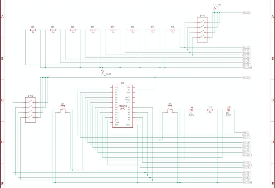
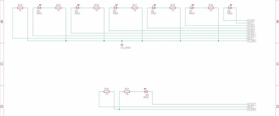
The images above are the circuit view and schematic diagram for my circuit. The schematic diagram was generated automatically by Tinkercad based on the circuit view I built. I connect the first 6 user input bits to analog input pins A0-A5 in ascending order, with the least significant bit going on A0. I connect the 7th bit to pin 2. Each of these bits are selected by flipping switches in series with pull down resistors. The start button and stop button are connected to pins 3 and 4 respectively. I will use the Arduino's built in pull up resistors to read the buttons. The output bits are then connected to pins 5 through 11 in ascending order. These are put in series with an LED and a 1k ohm resistor, which will be used to read the time remaining. The alarm is connected to pin 12. The rightmost LED in the circuit view represents the alarm. I will add a couple more LEDs as well as a DC buzzer, which was not available in the Tinkercad software at the time I made this simulation.
Program
The design of the circuit described above is quite simple because the program of the microcontroller is capable of handling a large portion of the logic that goes into this circuit. I developed the program in Notepad++ before simulating in Tinkercad and ultimately implementing it in Arduino IDE. The PDF below is the program I used for this circuit with comments explaining different parts. Make sure to scroll to view all pages.
Application is no longer available.
Once I got the program above to function in the Tinkercad simulator, I began building my circuit.
Building


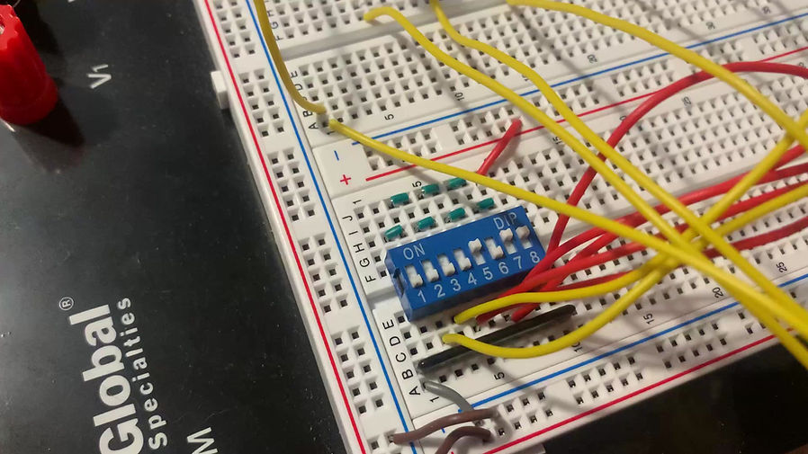
The image above on the left is the circuit after I placed the input components. It features a component with 8 switches and two push buttons. Because my timer is only seven bits, I will only use switches 2-7, in my circuit, and switch 1 will be irrelevant to my circuit. The pins on the top half of the switches are all connected to 5V. The pins on the bottom half of the switches are connected to a 1k network resistor that serves as a pulldown resistor. The input value for each switch will be read in between the pulldown resistor and the bottom of the switch. The push buttons are each grounded. The input value for each button will be read across the button, using built in pull-up resistors for each pin.
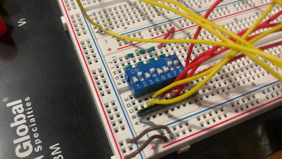
The image above on the right shows the circuit after I connect the MCU and its input pins. In order to create the appropriate amount of space between my switches and buttons, I had to first connect the switch pins to the middle of the circuit before I extend them to their proper positions.

I then connected seven amber LEDs each in series with a 1k ohm resistor in the middle section of the circuit. These LEDs will be used to read the time. The anode of the LEDs were connected to their corresponding pins. At the top of the circuit, I connected the alarm output pin to three red LEDs and a DC buzzer in parallel. Each of the LEDs are put in series with a 1k ohm resistor. The construction of this circuit is far more simple than some of the projects I've made without a MCU. This is because the MCU can handle practically all circuit logic, meaning only components for user input and output are necessary to place on the board.
Final Demo and Conclusion
In the video below, I use the switches to set the time to the maximum of 127 seconds. When time runs out, I let the alarm play until it is disabled automatically after 20 seconds. I increase the play speed of the video at various points. I compare the time on my timer to a timer on my computer. Because it is difficult to begin both timers at the exact same instant, depending on when you pause the video, the times displayed may or may not be one second off from each other. However, the important thing is that they both keep time with each other throughout the 127 seconds.

In the video below, I set the time to eleven seconds. When the timer runs out, I press the stop button before the alarm stops automatically.
In the video below, I set the time to 83 seconds. I stop the timer soon after pressing play, before time runs out. I then start the timer again and do the same. I then change the time to 19 seconds. I hit the play button then let it run for a little before stopping it.
Overall, I am happy with how this project turned out, and I was able to make this without ordering any parts. One way to upgrade this project would be to eliminate binary numbers completely. This would be done by having the user input a number in decimal, and have an output display in decimal. For example, the input could be a numeric keypad input, and the output could be an LCD display. These are components that I would like to incorporate into future projects, and I would love to design and program an upgrade to this project at some point.