
Introduction
The goal of this project was to design and build a circuit that uses an audio trigger to toggle a light-emitting diode, or LED. I wanted to build this circuit without using a microcontroller, and only using components that I already owned. I wanted the LED to toggle on and off at the audio level of a clap, but not at the level of casual conversation. In this circuit, I will create an audio signal of the environment. The louder the environment is, the greater the voltage of the audio signal will be. By observation of this audio signal, I will choose a reference voltage such that when the voltage of audio signal surpasses the reference voltage, the LED will be toggled.
Design

The image above is the first stage of my design. It features the power supply, the microphone voltage divider, and an inverting amplifier for the audio signal taken from the microphone. The audio signal is represented by the Vmic label in the diagram. The microphone is represented by the resistor labeled Rmic. As sound waves travel through the microphone, it causes the diaphragm of the microphone to vibrate. This vibration changes the impedance of the microphone. The voltage between this divider varies due to this changing impedance. This changing voltage is then used as the AC audio signal. I then send this signal to a blocking capacitor to prevent DC from being amplified, and then to an inverting amplifier. Based on the labels within the diagram, the formula for the gain of an inverting amplifier is R7/R6. Therefore, this amplifier has a gain factor of 1000. The reason why I want to amplify this signal is because it will be easier to set the reference voltages that will trigger the circuit if the signal is on the order of a few volts rather than a few millivolts.

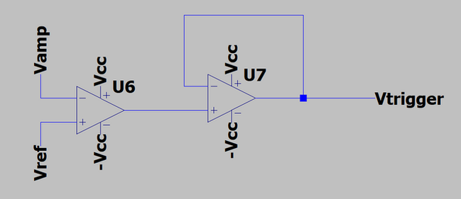
The image above shows shows a voltage divider and an op amp comparator. The trigger should be activated when the soundwave exceeds the desired reference voltage. At this point, I hadn't chosen resistor values for the dividers that determine the reference voltage because I needed to see how the sound wave behaves on my oscilloscope before I determined what my reference voltage is. I will eventually send the trigger to a 555 timer in monostable mode. I will explain why I do this later, but the important thing about that for now is that the 555 timer is activated when the trigger goes low (which is generally considered to be 0 V to 0.7 V). Because of that, on my op amp comparator, I output 5V when the audio signal is less than my reference voltage, and I output 0 V when the audio signal is greater than my reference voltage. One thing that this design is assuming is that the audio signal will always have a peak in the positive half of the voltage spectrum. When I later measured the audio signal, if I had discovered there are sometimes exclusively negative peaks, then I would have needed to create a second trigger for negative voltages, and then sum those two triggers together. However, I did not expect this to happen, and so I did not deem it necessary to account for this in my original design.

The image above shows a 555 timer in monostable mode. I use a 555 timer in this circuit because I want to protect the output from oscillating rapidly between low and high voltages. If the audio signal rapidly exceeds the reference voltage, goes below the reference voltage and then returns above the reference voltage, then that would toggle the output twice and no change will be made. In order to prevent that from happening, I use a 555 timer in monostable mode. The output of the timer will be low until Vtrigger goes from high to low. When this happens, the output will go high for a fixed period of time, rather than being dependent on the comparator at any given instant. This concept of protecting a circuit from quick and undesired fluctuations in output is called debouncing. The time period the output is high is determined by the resistor and capacitor values that are connected to the discharge and threshold pins. The formula for this time is t = 1.1*R*C. Therefore, if I use a 10 uF capacitor and a 100k resistor, the output will be fixed at a high value for 1.1 seconds. I figured this would be more than enough time for the audio signal to settle after it is affected by the input.

J
K
Ultimately, I use a JK flip flop chip to toggle the output. If I connect the J and K pins to +5V, then the chip will be in toggle mode. This gate is negative edge triggered. This means that when the output will be toggled when the clock pin goes from high to low. However, the 555 timer is stable at 0V and goes up to 5V for 1.1 seconds when triggered. This would result in the flip flop not being toggled until 1.1 seconds after the timer is triggered. I eliminated this issue by sending the output of the timer to an inverter. This means that the output of the clock is stable at 5V, and it goes down to 0V for 1.1 seconds when triggered. Because the flip flop is negative edge triggered, it is unaffected when the clock returns back to 5V after 1.1 seconds. The output of the flip flop is then sent to an LED in series with a resistor.
Building


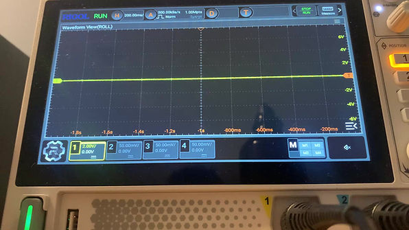
The image above on the left displays the microphone voltage divider and the inverting amplifier for the audio signal. In the video on the right, I play a 1 kHz audio signal, and measure the output of the amplifier. The response of the amplifier confirms that it is working properly.

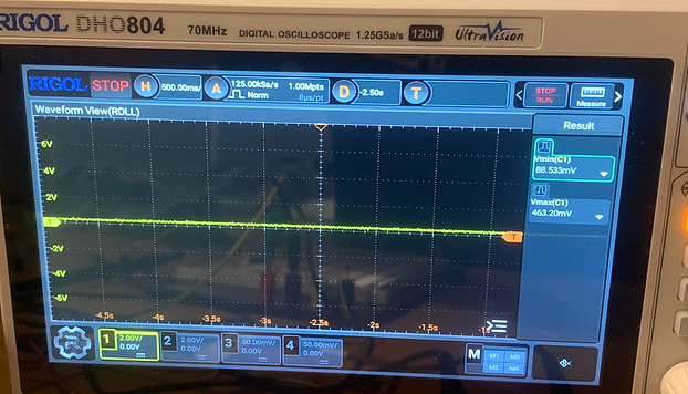
In the video above, I am still measuring the output of the amplifier. I view the response when I clap at varying levels of loudness. By observation, the peaks from every clap are both in the positive and negative voltage spectrum. Because of this, I didn't need to add any circuitry that would involve negative peaks. The strength of the signal in volts can be seen on the right of the oscilloscope display. I didn't want to choose a reference voltage too low because I didn't want casual conversation to trigger the circuit. I also didn't want to choose a reference voltage too high because I wanted a clap at reasonable strength to trigger the circuit. Based on the max heights of the peaks, I figured that 2 V would be a good reference voltage.
In the image on the right, I have added the voltage divider that will give me the 2 V reference voltage (on the top right of the circuit), and the op amp comparator for the amplified audio signal and the reference voltage (bottom left of the circuit). I needed a separate op amp for the comparator because I connect the negative power rail to ground instead of -5 V. This is because the output of the comparator will go to the 555 timer, which is a digital component that is only built to tolerate non-negative voltages.


The image above shows the output of the op amp comparator when I clap. In order for the signal to be considered logic low, the signal must go below 0.7 V. This signal doesn't even get below 1 V. This is bad because this signal would not trigger the 555 timer. This is likely happening because the output current is not high enough to drive the output voltage down to 0 V before the audio signal goes below the reference voltage again. However, one thing that I wanted to check first was the stability of the reference voltage when the pulse occurs.

The image above shows a measurement of the reference voltage when I clap. This voltage is clearly very unstable, and fluctuates well below 0 when the circuit is triggered. Fluctuations in the negative direction of the reference voltage likely weren't causing the problem that I was trying to solve. In theory, if anything, they would help solve the problem by possibly giving more time for the audio signal to be greater than the reference voltage, allowing the output of the comparator get closer to 0 V. However, out of curiosity, I wanted to see what the reference voltage and output of the comparator would look like if I sent the reference voltage to a buffer before I sent it to the comparator.


The image above on the left shows the output of a buffer of the 2 V reference voltage when I clap. The voltage is much more stable than without the buffer, however it now has a positive pulse. The output of the comparator can be seen above on the right. The output appears to be relatively unaffected by buffing the reference voltage. The minimum voltage does not go any higher or lower than when the reference voltage was not buffed. This means I still needed to figure out a way to get the output of the comparator to go lower. The negative power rail of the comparator op amp was still connected to ground, and I wanted to see if I could pull the pulse down more if I connected it to -5 V instead.

The image above shows the output of the comparator when I use -5 V instead of ground for the negative power rail. The output goes much lower, which is good. However, it also goes well below 0 V. This cannot happen because I needed to send the pulse to the trigger of a 555 timer. At this point, the decision of whether to keep the buffer on the reference voltage seemed arbitrary. I decided to I keep the it to avoid the large negative fluctuations of the reference voltage that could drive the output voltage lower. I also figured the improved stability of the reference voltage would be good for the stability of the power rails of the breadboard. I thought it would be better to work with a voltage that went too low, rather than one that didn't go low enough, so I kept the -5 V on the negative power rail of the comparator. The first idea I had to fix this would be to send the output of the comparator to a new op amp buffer with the negative power rail connected to ground. This would mean that in theory the op amp would output 0 V at minimum. That would look something like this:

The image of the oscilloscope above shows the output of a buffer of the op amp comparator. This buffer has its negative power rail grounded. This results is even worse than when I grounded the original comparator, as the lowest point barely goes below 2 V. Thinking about it more, these results make sense. If a 5 V potential difference on the power rails of the comparator couldn't get the output below 0.7 V, then there's no reason why a buffer, powered the same, would be able to do it. If I could use a 10 V potential difference on the power rails of the comparator while keeping the output between 0 and 0.7 V, it could work. In order to do this, I used a negative clipper circuit:

In the image above, the leftmost part of the circuit is the op amp comparator. The part second to the left is the voltage divider that will determine the bias voltage that will be applied to the clipper circuit. This bias voltage helps determine what voltage value to clip the signal at. In theory, having a Vbias of 0.7 V would clip the signal at 0 V, but I figured I would likely determine this value experimentally. I then send this bias voltage to a buffer to stabilize it. Then, on the rightmost part of the image above, is the actual negative clipper circuit. Vtimertrig represents the trigger that will go to the 555 timer.


The image above on the left shows the circuit with the negative clipper. I take a value of 0.8 V from voltage divider in the bottom right and send it to a buffer. The output of the buffer is then connected to the anode of the diode. In the video above on the right, the oscilloscope is measuring the output of the clipper circuit with a 0.8 V bias. It is tough to read the measurement on the oscilloscope due to the video quality, however the minimum voltage of the signal was still going almost as low as -50 mV. Because of this, I needed to increase the bias voltage on the clipper.
The video on the right shows the output of the clipper circuit when the bias voltage is 1.3 V. The output goes from a logic high voltage (2-5 V) to a logic low voltage (0-0.7 V). This means that I can sent this signal to the trigger of the 555 timer.


In the image above on the left, I have added the 555 timer in monostable mode. Given the resistor and capacitor values I have chosen, when the trigger goes from high to low, the output of the timer should go from low to high for 1.1 seconds. In the video on the right I measure the output of the timer. When I clap, the output goes from low to high for about 1.2 seconds before automatically falling back down. In practice, it is not important for the clock output pulse time to be exactly 1.1 seconds because that was an arbitrary value to begin with. Any value for the delay could work as long as the time is long enough to prevent the circuit from triggering multiple times from a singular clap, and short enough such that a quick second clap would also trigger the circuit. According to the oscilloscope, this signal was still going lower than -100 mV. This meant I had to clip the output of the timer as well.

The image above shows the output of a clipper circuit for the timer when I bias the circuit with the same buffer that provides 1.3 V when I do not trigger the circuit by clapping. The signal should be low the entire time because I do not trigger it. However, the voltage goes over 1.1 V because there is too much noise. This noise was likely being caused by op amps, and I had to get rid of it in order to properly define the signal.


The image above on the left shows the added negative clipper for the output of the timer. The clipper is biased with 1.2 V directly from the voltage divider. The image above on the right displays the output of the clipper when the circuit is not triggered. The signal stays between 0 V and 0.7 V, which is exactly what I wanted.
The image above displays the output of the timer in yellow, and it measures the 1.2 V bias voltage in blue. The output of the clipper behaves the way I want, going from a logic low to a logic high when the circuit is triggered. The bias voltage of the clipper is also relatively stable when triggered. It does make a slight jump up, but that is not an issue as long as it prevents the output of the timer from going negative. This means the signal is good to send to the inverter gate. The inverter gate is necessary so that the negative edge triggered clock pin on the JK flip flop can be triggered immediately, and not after the 1.1 second delay.

The image above on the left shows the inverter gate and the JK flip flop added to the circuit. The inverter gate flips the output of the timer's clipper circuit. The output of the inverter gate goes to the clock pin of the JK flip flop. The J and K pins are both connected to +5 V so the chip is in toggle mode. The video above on the right shows the output of the JK flip flop when the circuit is triggered. This output is behaving exactly as I would want it to, so I was ready to connect the LED.
The image on the right shows my final design. I decided to clean up the voltage dividers by using fewer resistors. Then I connected the output of the JK flip flop to a LED in series with a 100 ohm resistor.

Final Design, Demo, and Conclusion
In the video below I test the circuit with and without a YouTube video in the background to simulate how the light would behave during casual conversation.

Even when the background noise is on, the light only toggles when I clap. This is good because it was one of my goals for this project. Overall, I am happy with how this project turned out. I didn't have to use a microcontroller, and I didn't have to order any parts. I ran into a few more issues than I expected, which was mostly a result of combining op amps with digital components. I ended up using more board space than I originally wanted, but it definitely got better after I swapped out the large voltage dividers for more specific values. By the end, most of the extra space was taken up because I wanted to protect my digital components from negative voltages. Figuring out that aspect was the most difficult part, but I also gained the best experience working through those issues. I got great practice manipulating the signals to fit my desired parameters.


J
K